
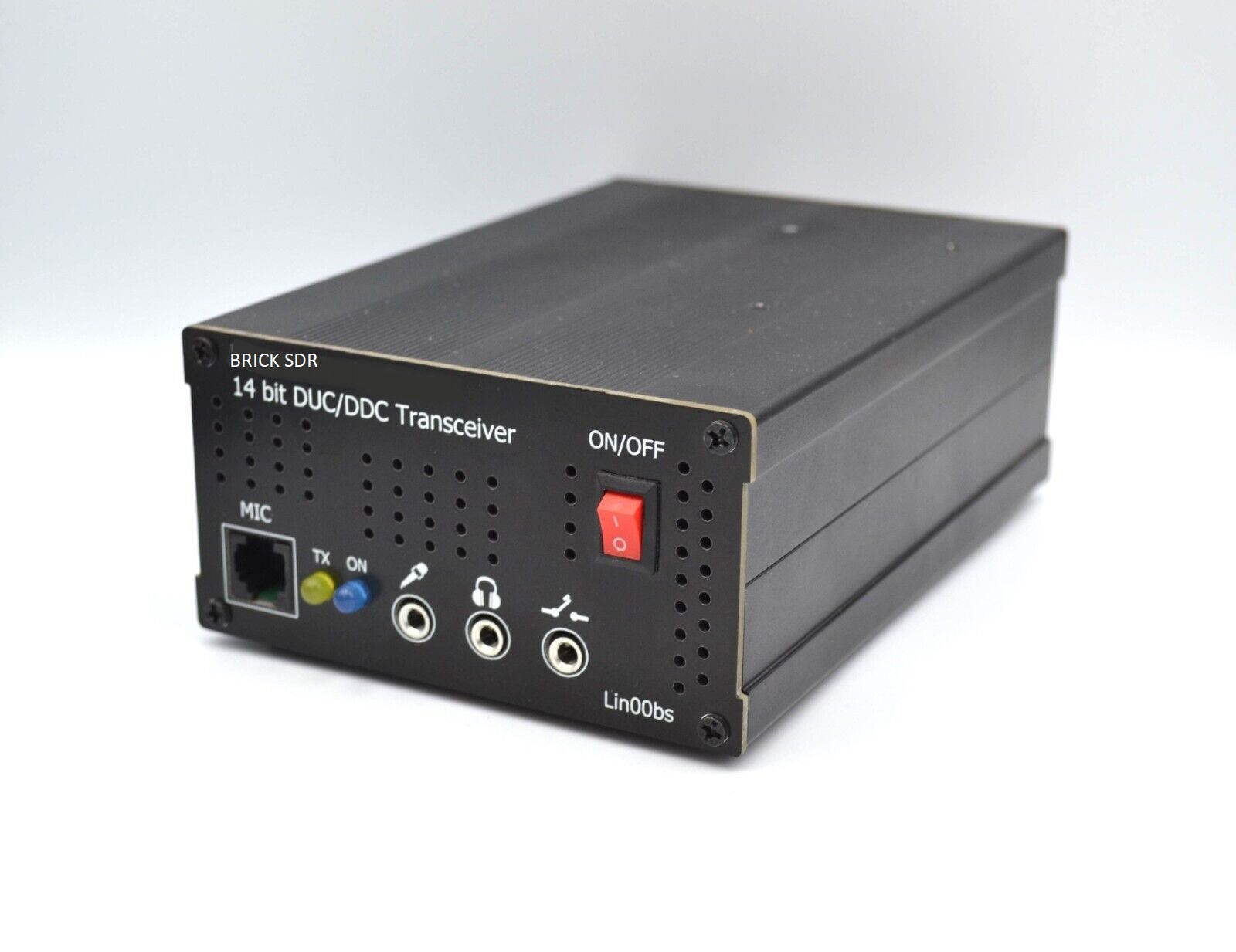
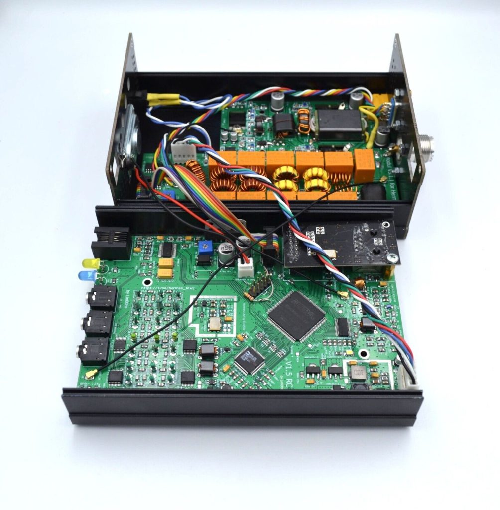
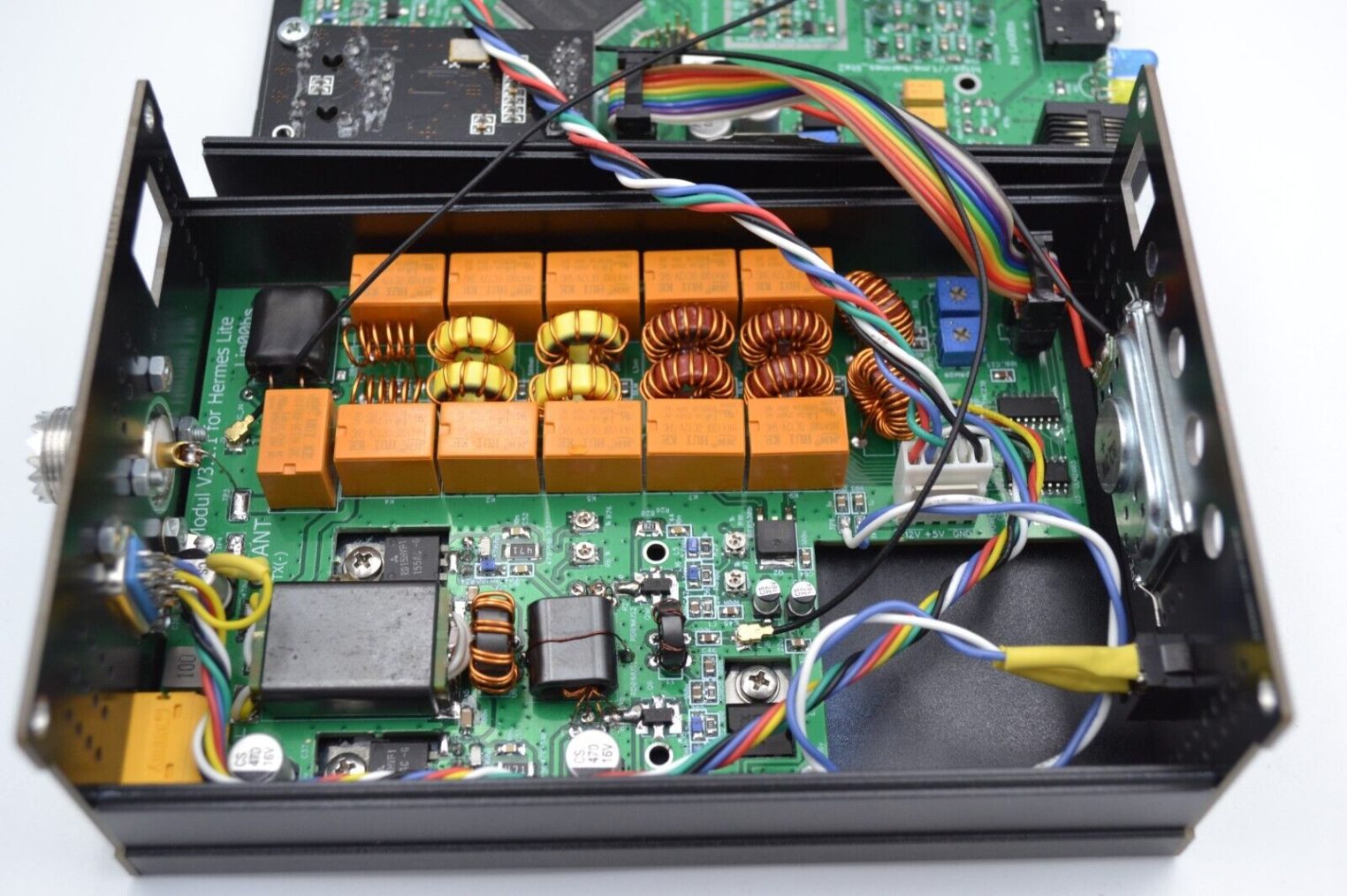
Brick SDR (Software Defined Radio) is a modern radio technology that uses direct digital signal processing DUC/DDC. The transceiver includes two printed circuit boards, on which the receiver, transmitter, output stage, ATT, LNA, BPF and LPF filters, speaker etc. are integrated together.
Inspiration
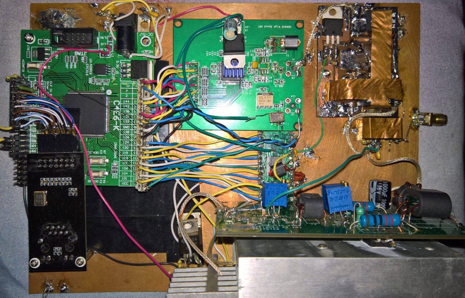
Existing SDR transceiver project are Hermes, ANAN 10E, Hermes-Lite 2, Orion etc. These devices are quite outdated and some components such as FPGA, ADC are simply no longer available, and one radio amateur Sergey EU1SW assembled a transceiver on separate debug boards, on which were located separate parts responsible for reception, transmission, logic, network adapter, codec and other. You can see its design here. When I saw such a solution, I immediately wanted to develop one printed circuit board, on which all the necessary elements would be located, which would provide everything most necessary for a radio amateur on HF in the ranges of 160 – 6 m.
Realization
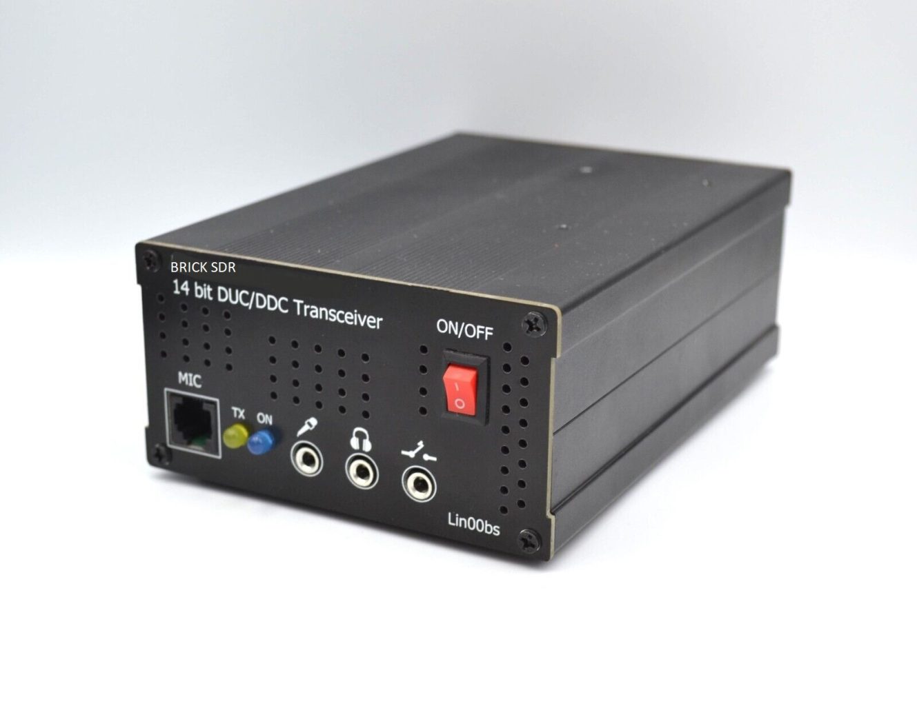
I had an idle case measuring 150x105x55 mm, which prompted me to create a printed circuit board for the transceiver. Since there is a lot of space in this case, it was decided to also develop an output power amplifier. The ideal overall power seemed to me to be no more than 25 W. Therefore, the power amplifier operates on two RD16HHF in a push-pull circuit. And so it turned out. The name Brick SDR was not long in coming, the design was very much like a brick or a black box. The location of the connectors is in their places, in the front are the manipulation elements (microphone, headphones), the power button. At the back is a power connector, antenna, a slot for controlling external devices such as a external power amplifier, (SMART PA), antenna switch, etc.
Basic specifications
- Supply voltage 12 – 15 VDC
- Frequency range RX/TX 100 kHz – 55 MHz (MARS) without restrictions in hardware
- Integrated switchable -10 dB ATT and +15 dB LNA, BPF and LPF filters
- Output RF power max. 25 W
- Power consumption when receiving approx. 400mA
- Power consumption during transmission approx. 5 A
- 14-bit ADC and separate 14-bit DAC
- Fast Ethernet
- TCXO frequency stabilization
- LED indication of the FPGA is ready
- SWR/PWR meter
- Integrated parallel interface for external control PA, antenna switch etc. (open collector ULN2003) or BCD (Yaesu, Elecraft, etc.) HEX (DB-9 ACC connector)
- “Pure Signal” out of the box (no external input, needs testing)
- 2 Receivers 1 Transmitter
- SW, GW compatibility and functionality (protocol 1) with PowerSDR, Thetis, Quisk, ConsoleSDR and other
- Total external dimensions in the box 150 (w) x 55 (h) x 100 (d) mm
- Weight approx. 750 g
Differences and improvements over other such constructions
- Integrated switchable -10 dB ATT and +15 dB LNA, BPF and LPF filters
- LED indication of the RX/TX
- Integrated parallel interface for external control PA, antenna switch etc. (open collector ULN2003) or BCD (Yaesu, Elecraft, etc.) HEX (DB-9 ACC connector)
- Integrated speaker and mic connector as Yaesu MH-48, 32 etc.
- “Pure Signal” out of the box (no external input, needs testing)
- 2 Receivers 1 Transmitter
- Protection of the EXTTR output (PTT)
- Protection of PTT input with optocoupler
- Replacement and addition of some components for easier manufacturability in the EU
- STM32 microprocessor for ATT, LNA, bandpass, LPF control
- Robust aluminum box with better heat dissipation
- It is delivered completely assembled and tested. It’s a single purpose build, not a kit, but if you think, you can assemble it itself, you can ask of blank pcb’s and some components
Description of connectivity
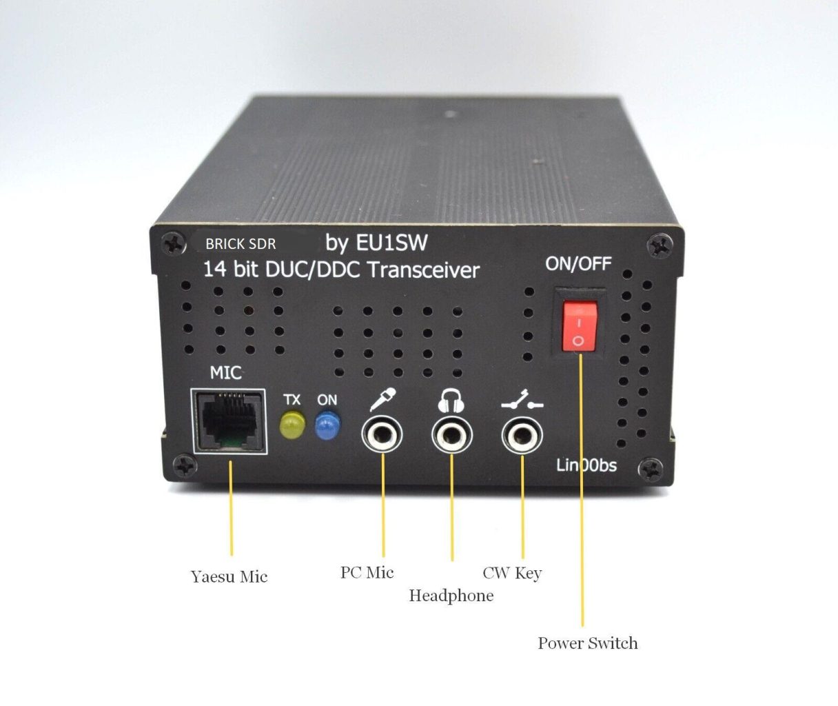
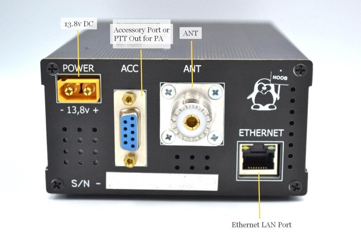
Views of the overall structure
ACC connector wiring description
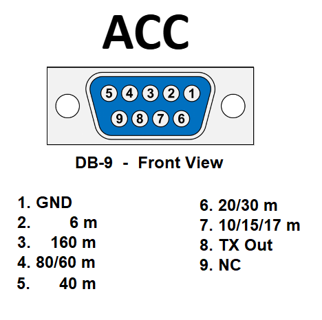
Control of an external PA amplifier or Accessories
The TX out or ACC connectors on the rear panel can be used to connect and control an external PA amplifier. Using the TX out connector, only the external PA can be switched to broadcast mode (keying). This is done by connecting the PTT signal on the PA to ground (GND). Using the ACC connector, it is possible to key the external PA and automatically switch frequency bands. All outputs are biased by the power supply and the required band-output is grounded when in use (open-collector). If you need BCD-HEX output as in Yaesu, Elecraft, just PM.
Frequency detection: Some PA amplifiers have a built-in frequency detector, such as my SMART PA 100W HF/6m, that monitors the output signal from the transceiver. Based on the detected frequency from the input signal during transmission, the amplifier automatically switches to the appropriate band.
Digital communication: This output is not default and can be realised on request. Based on the data frame that the BRICK SDR sends over the parallel line towards the PA amplifier. The data frame format is Binary-coded decimal (BCD). BRICK SDR uses a BCD-Code for communication, which is output on the ACC connector, which is located on the rear panel. The data frame contains information about the frequency and is transmitted on the TX signal every time it changes (even during keying). The description of the signals is given on screenshot.
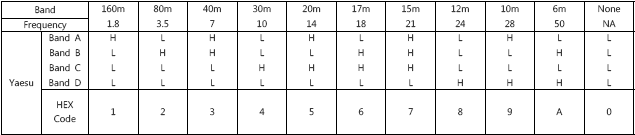
Its mean for example band 40m outputs A,B hi and C,D low.
Analog signal: Default output signal for control external PA is open-collector outputs in BRICK SDR. A separate signal is used for each band, as shown in the image above.
Robust mechanical construction
The basis of the mechanical construction is an aluminum profile with dimensions of 150 x 55 x 100 mm and a wall thickness of 4 mm. The side panels are realized as PCB with high-quality printing. Copper is left on the inside of the PCB side panels, which is electrically connected via four screws in the corners to the aluminum profile. All this ensures sufficient shielding for the operating frequencies of the SDR itself. The entire structure also ensures sufficient cooling for continuous operation.
Commissioning
For maximum and optimal use of the BRICK SDR hardware, perfect knowledge and settings of the utility program (console) that controls the BRICK SDR is required. If set up and operated incorrectly, some parts of the unit may not work properly or at all.
BRICK SDR is compatible with all software supporting the OpenHPSDR 1 protocol. The list of popular utilities for controlling and using BRICK SDR as a transceiver. The most elaborated currently is probably Thetis .
In the utility (console) BRICK SDR is selected and connected as “HERMES”, “Hermes-Lite”. No special settings are required, the program works by default. Apollo check box must be checked to display output power and SWR correctly.
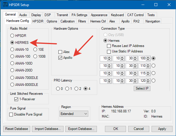
I recommend using PowerSDR mRX for several reasons:
- this is a finished program, all bugs are fixed
- it was created specifically for this firmware
Real operation
Sample when receiving in the SDR Console program:
Sample when receiving in the Thetis program:
In conclusion
This BRICK SDR design was not created for the purpose of creating some cheap Hermes clone, but also with the aim of improving, increasing the overall efficiency of the design, based on the availability of components today. So it’s not a kit.
If you want to order BRICK SDR, use the following link…
UPC: 4260610689996
Schematic and source files
Important note: These documents are intended for your own personal use only. EU1SW and the operator of this site bears no responsibility for any financial losses, damage to property or health arising from the use of these documents.
Links
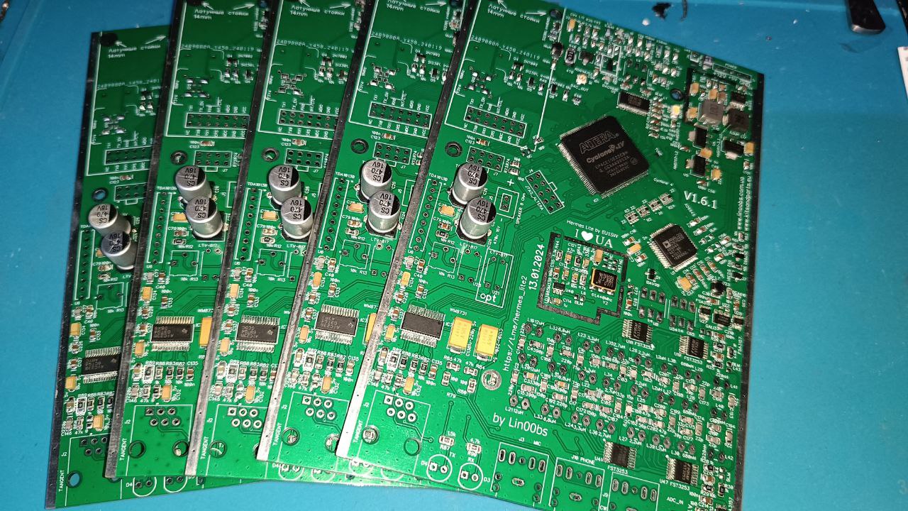
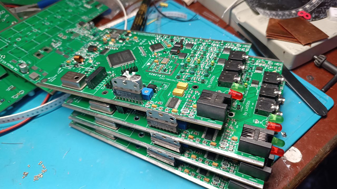
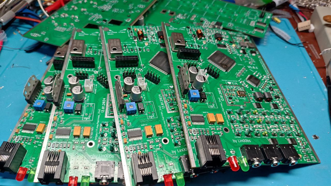
Production pictures
Good morning,
User of Hermes-Lite, I would be interested in your TX RX Brick SDR. Could you tell me what the availability is, the price delivered in France, and the ordering methods.
Kind regards, Bernard F5DYS
Hello, you can find in Online Shop -> http://www.kitsandparts.eu
As i know, there will be two sdr available in one week.
Is the Hemes main board available for sale, populated with all of the components?
I don’t require a power amplifier or a box.
73’s
Dale
ve3aam
No, sorry. There is only finished device Brick2 SDR available.
When will you have the Brick2 available for sell? or it won’t be available anymore?
should be available by the end of February.
Would be nice to have a separate RCA jack for PTT of an Amplifier.
In Brick SDR this connector was at the seller/buyer’s choice, RCA or DB9. As practice has shown, one simple RCA is not in demand, because the DB9 also outputs the bands control etc., which is in demand in most cases, so in Brick2 it was decided to use DB9, so to speak, “out of the box”.
Hello
Anyone use the XPA125B with the BRICK2 ?
Kind regards
Bonjour,
Quelqu’un utilise le XPA125B avec le BRICK2 ?
Cordialement
Hello,
Can the Brick2 be connected to the Expert 1.3K-FA amplifier, will the bands auto switch when you change bands?
How to connect ?
Is there any manual ?
Thanks for reply.
73 Rudi
yes it can, as any othe trx.
Hi
Work the BRICK whit N1MM aplikation ?
Whith CAT they have?
i think it does not mather wich one logger to use, Thetis or PowerSDR etc. working with any.
There is Pure signal port ? I could not see one one the pictures.
Brick1 does not have and not more produced. See Brick2 SDR -> https://linoobs.com.ua/brick2-sdr-remote-hf-transceiver-160-6-m-15w/
I noticed your eBay site have listed. The power output of this SDR is 15 W pout on this site it says 25 W Just wonder which way which one it is.
Thanks
this is the first version, on eBay is Brick2, with Pure Signal, reduced power output and others changes.
Hello Anton,
I have a Brick2 SDR 14-bit, detected by Thetis as:
Hardware: Hermes
Protocol: Protocol 2
Firmware/gateware version shown by Thetis: 10.5
Before buying an external RF sampler, I would like to confirm exactly whether my unit is fully prepared for PureSignal.
Could you please clarify the following points?
Does the Brick2 14-bit with firmware 10.5 fully support PureSignal in Thetis?
Is the rear SMA connector marked ANT/PS-A electrically routed as the PureSignal feedback input while transmitting?
Does PureSignal require:
any internal jumper;
hardware modification;
different firmware/gateware;
or a specific Brick2 hardware revision?
Does the Brick2 internal 0–31 dB attenuator operate on the PS-A feedback signal during transmission?
Does Thetis control this attenuator through:
ATT on TX;
S-ATT;
Auto Attenuate;
or another specific setting?
What is the maximum safe RF input level, in dBm, at the ANT/PS-A SMA connector?
What feedback level do you recommend at the PS-A input for correct PureSignal operation?
I plan to use an external sampler with −55 dB coupling, installed after a 500 W linear amplifier.
Its approximate output would be:
400 W: about +1 dBm
500 W: about +2 dBm
600 W: about +2.8 dBm
Can this sampler be connected directly to PS-A while using the Brick2 internal attenuation, or should I add an external fixed attenuator for protection?
Can PureSignal correct the complete chain when the sampler is placed after the external amplifier?
Brick2 → amplifier → RF sampler → antenna/load
Can ANT/PS-A be used for feedback while the normal receive antenna is connected to the main RX antenna input, or is PS-A shared with another receiver path?
Are there any necessary Thetis settings apart from disabling Receive Only and enabling PureSignal/Linearity?
Are there any known limitations or bugs with:
Brick2 14-bit;
Protocol 2;
firmware 10.5;
and recent Thetis versions?
Is firmware 10.5 the recommended version for PureSignal, or should I install another firmware/gateware version?
Is any special TX/RX sequencing or delay required to protect the PS-A input during PTT transitions?
In case my hardware revision is not compatible, what exact modification or firmware change would be required?
I would appreciate a clear confirmation because I do not want to connect an RF sample to the SMA input until I know its maximum permitted level and the correct attenuation settings.
Thank you very much.
Best regards,
Jorge
Hello,
Thank you for reaching out. Here are the answers to your questions:
PureSignal support / Hardware preparation: It all depends on where and when you purchased your Brick2 unit.
Rear SMA (ANT/PS-A) routing: Yes, it is electrically routed as the feedback input during transmission.
Jumpers / Modifications / Firmware: As mentioned in point 1, this depends on the specific hardware revision and purchase date/source of your unit.
Internal Attenuator: Yes, the internal 0–31 dB attenuator operates on the PS-A feedback signal.
Thetis Control: Yes, Thetis controls this attenuator accordingly.
Maximum Safe RF Input: Like any standard receiver input, the maximum safe level is 50 mV.
Recommended Feedback Level: I cannot give a specific recommendation for the ideal level as I do not personally use the PS-A input.
To help determine if your specific unit requires any modifications or different firmware, please let me know when and where (from which vendor/seller) you purchased your Brick2.
Best regards,
Hello Anton,
Thank you very much for your detailed reply.
Here is the information about my Brick2:
Vendor: Kits and Parts (Germany) – https://kitsandparts.eu/de/
Purchase date: 15 November 2025.
Serial number: I could not find any serial number on the rear panel. It may only be located inside the unit.
Could you please let me know whether this hardware revision:
is already fully prepared for PureSignal,
requires any hardware modification,
or requires a specific firmware version?
If you happen to know, I have one small additional question (only if it is easy to answer):
For a 500–600 W HF amplifier, is there any RF sampler attenuation that you generally consider appropriate (for example around -50 dB or -55 dB), or is this entirely left to the user’s own setup and adjustment?
I completely understand if there is no single recommendation—I just wanted to ask in case there is a commonly used starting point.
Thank you again for your time and assistance.
Best regards,
Jorge
Yes, this specific model requires a firmware update.
Regarding the RF sampler, I do not know of any generally accepted or specific standard models, but units with −50 to −60 dB attenuation are commonly found online.
Thank you, Anton.
Could you please tell me which firmware version my specific Brick2 requires for PureSignal, and how the update must be performed?
Is the firmware file and update procedure available from you?
Also, after the update, will the PS-A input and its internal attenuator be fully controlled from Thetis without any additional hardware modification or jumper change?
contact to https://kitsandparts.eu/